| |
| |
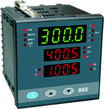
| DIFFERENCE TEMPERATURE / PROCESS VALUE INDICATOR ----------------------------------------------------------FC96A-Δ |
| |
|
- Two universal inputs A, B
- Difference, Average , Max, Min functions
- 0/ 1/ 2 / 3 / 4 alarms for input A, input B or
function selected
- Isolated 2 x 0/4~20 mA or 0~10 V DC
retransmission outputs corresponding to
input A, input B or function selected
- 24 V DC transmitter supply
- RS485 / MODBUS RTU
- 85~265 V AC or 20~35 V DC supply
- 6 alarm types
|
| |
| Specification All sepecifications at ambient of 25 °C, unless specified otherwise |
| |
| INPUTS |
|
| No. of Inut |
2(input A, input B) |
| Input group 1 |
|
| (common for both inputs) |
|
| Thermocouple |
B, E, J, K, N, R, S, T |
| RTD |
Pt100, 3-wire |
| Voltage |
0~50 mV |
| Current |
0~20 mA, 4~20 mA |
| Input group 2 |
|
| (common for both inputs) |
|
| Thermocouple |
B, C, D, E, G, J, K, N, R, S, T |
| RTD |
Pt100, 3-wire, Cu53 |
| Current |
0~20 mA, 4~20 mA,
Square root (for input 1) |
| Voltage |
0~50 mV
Through DIP selection
following voltage inputs are
available:
0~1 V,
0~5 V, 0~10 V,
0~10mV, 0~100 mV, 0~200
mV |
| Transmitter supply |
22 V nominal, 30 mA max |
| Range limits |
See Table1 |
| Accuracy |
See Table1 |
| Cold junction compensation |
Automatic |
| Sensor break Protection |
User programmable |
| INDICATION |
|
| Upper display |
4 digit, 7 segment
0.56" (14.2mm) red LED
display
Parameters :
Difference (A-B)
Maximum(A)
Minimum(A)
Average(A+B/2)
|
| Middle display |
4 digit, 7 segment 0.39"(9.9mm) green LED display
Parameters :
Setpoint 1
Setpoint 2
Input A
|
| Lower display |
4 digit, 7 segment 0.39" (9.9mm) green LED display
Parameters :
input A
Input B
|
| LED indicators |
Relay status
Setpoints
Communication
Function
|
| OUTPUTS |
|
| No. of relays |
0 / 1 / 2 / 3 /4 |
| Relay contact type |
NO-C-NC |
| Relay contact rating |
5A / 230V AC, resistive |
| SSR drive |
12 V DC drive signal for external SSR |
| No. of analog outputs |
0 / 1 / 2 (current or voltage) |
|
| Current output |
4~20 mA / 0~20 mA / 20~4 mA / 20~0 mA isolated from input |
| Maximum load for current output |
500 ohms |
| Voltage output |
0~10 V / user specified |
| Load for voltage output |
>10 Kohms |
| COMMUNICATION |
|
| Port |
RS485 |
| Protocol |
Modbus RTU |
| Slave ID |
User programmable (1~256) |
| PROGRAMMABLE PARAMETERS |
|
| Setpoint |
Full range(See Table 1) |
| Function |
Difference (A-B)_
Maximum(A)
Minimum (A)
Average(A+B/ 2) |
| Unit |
°C, °F, EU |
| Resolution |
User selectable
0.01, 0.1 or 1 for linear
input, 0.1 or 1 for
temperature |
| High scale |
Full range (See Table 1) |
| Low Scale |
Full range (See Table 1) |
| Digital filter |
A (minimum) ~ F
(maximum) |
| Hysteresis |
0~25 % span |
| Bias (for process variable) |
-50 to 50% of range limit |
| Relay assignment |
Corresponding to input A or input B or function selected |
| Alarm type |
a. Fullscale high alarm
b. Full scale low alarm
c. Deviation high alarm
d. Deviation low alarm
e. Inband alarm
f. Outband alarm
(c. to f. available for SP2,
SP3, SP4 only)
|
| Alarm mode |
Self reset or latched and can
be disabled at power on |
| Alarm acknowledge |
Front panel function used to
reset relay in alarm condition |
| Setpoint lock |
ON, OFF |
| Level lock |
ON, OFF |
| Relay action |
Reverse / direct |
| OTHER |
|
| Programming |
Through 3 tactile keys |
| Dimensions (in mm) |
96(H) x 96(W) x 100(D) |
| Mounting |
Panel mount |
| Panel cutout |
92 x 92 mm |
| Supply voltage |
a) 85~265 V AC, 50/60 Hz
b) 20~35 V DC(optional) |
| Power consumption |
4 watts maximum |
Operating ambient
temperature |
0~50 °C |
| Relative humidity |
Below 90%, non condensing |
|
|
| |
| |
| Table1 |
| |
| Sensor / Input |
Range Limits |
Range In Which |
Typical Accuracy |
Worst Case |
| (°C/ EU ) |
Accuracy Is Specified |
At 30 °C |
Accuracy |
| Low Scale |
High Scale |
Low Scale |
High Scale |
(°C / EU ) |
(°C / EU ) |
| Input Group 1 |
| Pt - 6% Rh / Pt - 30% Rh (B) |
400 |
1820 |
400 |
1820 |
±3 |
±5 |
| Chromel / Constantan (E) |
-270 |
850 |
0 |
850 |
±1 |
±3 |
| Iron / Constantan (J) |
-210 |
760 |
0 |
760 |
±1 |
±3 |
| Chromel / Alumel (K) |
-270 |
1372 |
-50 |
1200 |
±1 |
±3 |
| Nicrosil / Nisil (N) |
-270 |
1300 |
-50 |
1200 |
±1 |
±3 |
| Pt / Pt - 13% Rh (R) |
0 |
1760 |
400 |
1760 |
±2 |
±5 |
| Pt / Pt - 10% Rh (S) |
0 |
1760 |
400 |
1760 |
±2 |
±5 |
| Copper / Constantan (T) |
-270 |
400 |
-200 |
400 |
±1 |
±3 |
| Pt100, 3-Wire |
-200 |
850 |
-200 |
600 |
±0.3 |
±1.0 |
| Linear (0~50 mV, 0~20 mA, 4~20 mA) |
-1999 |
9999 |
-1999 |
9999 |
±5 EU |
±20EU |
| Input Group 2 |
| The following inputs are available in input Group 2 in addition to inputs of input group 1. |
| Tungsten - 5% Rh / Tungsten - 26% Rh (C) |
0 |
2320 |
0 |
2320 |
±3 |
±5 |
| Tungsten - 3% Rh / Tungsten - 25% Rh (D) |
0 |
2310 |
0 |
2310 |
±3 |
±5 |
| Tungsten / Tungsten - 26% Rh (G) |
0 |
2310 |
0 |
2310 |
±3 |
±5 |
| Cu53 |
0 |
180 |
0 |
180 |
±0.3 |
±0.5 |
| Linear (0~10 mV, 0~100 mV, 0~200 mV, 0~1 V, 0~5 V, 0~10 V) |
-1999 |
9999 |
-1999 |
9999 |
±5 EU |
±20 EU |
| Linear (4~20 mA ) with square root |
0 |
9999 |
0 |
9999 |
±10 EU |
±40 EU |
|
| |
| |
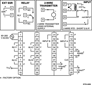
| Connection Diagram |
| |
 |
| |
| |
|
|