| |
| |
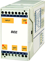
| SIGNAL ISOLATOR, DUAL OUTPUT--------------- ----------------------------------------------------------------BP4SI |
| |
| REPEATER POWER SUPPLY, 4~20 mA, FOR 2-WIRE TRANSMITTER WITH 1 OR 2 4~20 mA OUTPUTS |
| REPEATER POWER SUPPLY, 0/4~20 mA, FOR CURRENT SOURCE WITH 1 OR 2 0/4~20 mA OUTPUTS |
| |
| |
|
- Three port isolation between input, outputs and
power supply
- Provides two outputs from one 4 to 20 mA
transmitter or one 0/4~20 mA current source
- Line fault detection feature provides alarm facilities
- Transfer accuracy <0.1% of span
- 17~35 V DC / 85~265 V AC/DC power supply
- T section DIN Rail mounting
- Input protection option
|
| |
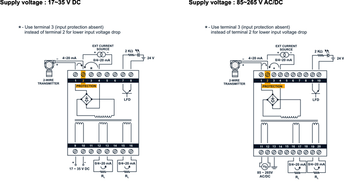
| BP4SI is an independently powered isolator which provides both a fully isolated DC supply for energising a 2-wire transmitter while also transferring the transmitter current to two separate isolated output circuits driving loads upto 1 kΩ. The input can also be a 0/4~20 mA current source. Line fault detection feature (also isolated) is provided by an open collector which can be used to activate an alarm. When the input cable is broken, no current flows into terminal 8/10 and line fault detection(LFD) output is OFF. When a current greater than 1 mA flows in the input, then LFD output is ON. Power supply required is 17~35V DC/ 85~265 V AC/DC. An input protection option is also provided. |
|
| |
| SPECIFICATIONS All specifications at ambient of 25° C, unless specified otherwise |
| |
| No. of input channels |
One |
| Input channel |
2-wire transmitter supply,
4~20 mA OR
4~20 mA current source OR
0~20 mA current soure |
| No. of output channels |
Two. |
| Input / Output signal |
4~20 mA OR 0~20 mA If
0~20 mA input is ordered, it
will work for 4~20 mA.
However, the power
requirement is higher. |
| Load resistance, each output |
0~1 kΩ |
| Isolation between input, |
1500 V DC/AC RMS, 1
minute |
| output 1, output 2 |
|
| and power supply |
|
| Voltage available for transmitter |
20 V typical at 20 mA |
| Voltage drop across input |
|
| from current source |
|
| With out protection |
1.5 V maximum |
| With protection |
3.0 V maximum |
| Input protection |
|
| Against overvoltage |
30 V DC maximum |
| Against overcurrent |
50 mA maximum |
| Power supply |
a) 85~265 V AC / DC, 50/60
Hz OR
b) 17~35 V DC |
| Power consumption |
|
| For C=0* |
|
| Supplying transmitter |
140 mA maximum at 20 V
DC |
| A=1* |
with a 20 mA signal 100 mA
maximum at 35 V DC with a
20 mA signal |
| From a current source |
115 mA maximum at 20 V
DC |
| A=1* |
with a 20 mA signal 80 mA
maximum at 35 V DC with a
20 mA signal |
| Supplying a transmitter |
180 mA maximum at 20 V
DC |
| A=0* |
with a 20 mA signal 130 mA
maximum at 35 V DC with a
20 mA signal |
|
| From a current source |
150 mA maximum at 20 V
DC |
| A=0* |
with a 20 mA signal 105 mA
maximum at 35 V DC with a
20 mA signal |
| For C = 1* |
< 5 VA |
| Transfer accuracy at 25 °C |
|
| for both outputs |
<± 0.1% of span |
| 4~20 mA |
Better than 16µA |
| 0~20 mA |
Better than 20µA |
| Line fault detection(LFD) |
Isolated transistor open
collector |
| output |
output |
| LFD characteristics |
|
| Input current < 0.2 mA |
Transistor OFF
Max permitted voltage: 26 V
DC Max OFF leakage current
: 150
µA |
| Input current >1 mA |
Transistor ON
Max permitted input current :
50 mA Max ON voltage : 1V |
| Temperature coefficient |
|
| of accuracy |
< 0.02% of span / °C |
| Common mode rejection ration |
150 dB typical |
| Ambient temperature limits |
-20°C to + 55°C
(Operating)
-40°C to + 80°C (storage) |
| Humidity |
5~95% RH, non-condensing |
| Enclosure |
|
| Material |
ABS plastic |
Dimensions C=0*
C=1* |
75(H) x 45(W) x 110(D) mm
75(H) x 55(W) x 110(D)mm |
| Mounting |
Snap on for 35mm DIN rail
to DIN 46277 |
| Terminals |
Accomodate 2.5 mm2
conductors |
| Weight |
< 250 grams |
| Protection |
IP 20 |
|
|
| |
| CONNECTION DIAGRAMS |
| |
 |
| |
|
|