 |
 |
|
| |
 |
| |
|
|
| |
Products
>>> Flow Sensor |
| |
|
|
1 2 3 4 |
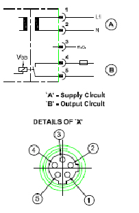
| Electrical Connection |
|
- Disconnect the power.
- Connect the unit as fallows
|
| |
|
| |
|
For the output circuit the same protective measure as for
the power supply
circuit must be taken.
- Insert a miniature fuse according to ≤ 5A fast acting.
- The permissible potential difference between supply
and output circuits is Max. 300V
|
| |
| Display Status |
|
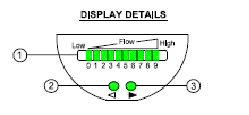
- After every power ON all LED'S light and go out again step by step
(During this time output is closed if configured as normally open)
- LED 9 flashes :- Current flow above the representation range.
- LED 0 flashes :- Current flow far below the representation range.
- If operating voltage is too low then there will be no display ( no LED light )
- The green LED's indicate the current flow (the LED's 0 To 9 represent
the range
between no flow and maximum flow)
|
| |
|
| |
| |
| |
| |
|
| |
|
|
| Copyright and Privacy Statement Bee Instruments |
|
|


